What is shown in the above figure?
a. compression ring 1
b. oil control ring
c. c...

Engineering, 19.07.2019 13:10 tiekert
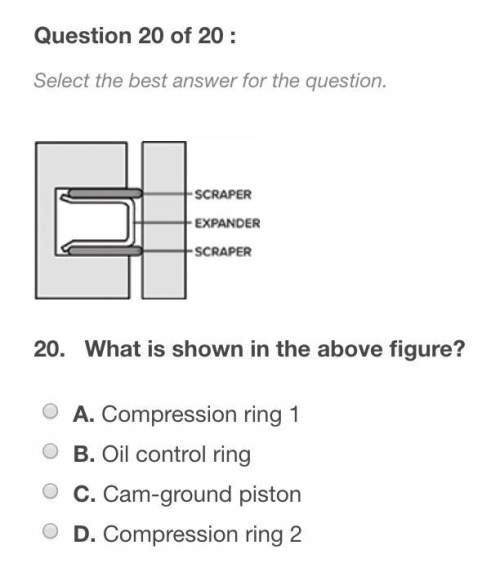
What is shown in the above figure?
a. compression ring 1
b. oil control ring
c. cam-ground piston
d. compression ring 2
Answers: 1
Another question on Engineering
Engineering, 03.07.2019 14:10
Amass of 1.5 kg of air at 120 kpa and 24°c is contained in a gas-tight, frictionless piston-cylinder device. the air is now compressed to a final pressure of 720 kpa. during the process, heat is transferred from the air such that the temperature inside the cylinder remains constant. calculate the boundary work input during this process.
Answers: 2
Engineering, 04.07.2019 18:10
Burgers vector is generally parallel to the dislocation line. a)-true b)-false
Answers: 2
Engineering, 04.07.2019 18:20
Avolume of 2.65 m3 of air in a rigid, insulated container fitted with a paddle wheel is initially at 264 k, 5.6 bar. the air receives 432 kj by work from the paddle wheel. assuming the ideal gas model with cv = 0.71 kj/kg • k, determine for the air the amount of entropy produced, in kj/k
Answers: 2
Engineering, 04.07.2019 19:10
Asteel wire of 2 mm diameter is fixed between two points located 2 m apart. the tensile force in the wire is 250n, if its density of steel is given by 7830 kg/m3 the fundamental frequency of vibration hz? ?
Answers: 3
You know the right answer?
Questions

Social Studies, 12.10.2020 20:01

Mathematics, 12.10.2020 20:01


History, 12.10.2020 20:01

History, 12.10.2020 20:01

Mathematics, 12.10.2020 20:01

English, 12.10.2020 20:01
Mathematics, 12.10.2020 20:01
History, 12.10.2020 20:01
Mathematics, 12.10.2020 20:01
History, 12.10.2020 20:01